DTC P0462: Fuel Level Sensor Circuit Low Input (Legacy & Outback)
- Perform test procedure. See TESTING PROCEDURE . Check operation of speedometer and tachometer. If speedometer and tachometer operate normally, go to next step. If speedometer and tachometer do not operate normally, repair or replace instrument cluster. See INSTRUMENT CLUSTER under REMOVAL & INSTALLATION in INSTRUMENT PANELS - LEGACY & OUTBACK
article in ELECTRICAL. Clear memory and perform verification procedure. See CLEARING DIAGNOSTIC TROUBLE CODES and VERIFICATION PROCEDURE
.
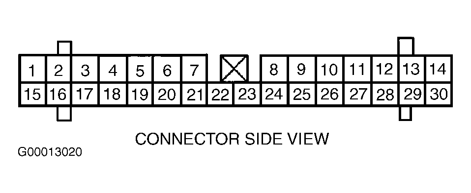
- Turn ignition on. Using a DVOM, measure voltage of Brown/Black wire by backprobing between 30-pin ECM electrical harness connector B136 terminal No. 27 and good chassis ground point. See Figure. If voltage is not less than 0.12 volt, go to next step. If voltage is less than 0.12 volt, go to step 4.
- Using a scan tool, monitor fuel level sensor signal while wiggling harness and ECM connector. If voltage changes less than 0.12 volt while wiggling harness and ECM connector, repair poor terminal contact in ECM connector. If voltage does not change less than 0.12 volt while wiggling harness and ECM connector, circuit has returned to normal. Check for intermittent conditions in connectors between instrument cluster and ECM. See INTERMITTENTS
in TROUBLE SHOOTING - NO CODES article. Clear memory and perform verification procedure. See CLEARING DIAGNOSTIC TROUBLE CODES and VERIFICATION PROCEDURE
.
- Turn ignition off. Remove fuel pump access hole cover located under right rear side of luggage compartment floor (wagon) or under right side of rear seat (sedan). Disconnect Black 6-pin in-line fuel pump connector. See Figure. Turn ignition on. Using a DVOM, measure voltage of Brown/Black wire by backprobing between 30-pin ECM electrical harness connector B136 terminal No. 27 and good chassis ground point. See Figure. If voltage is more than 0.12 volt, go to next step. If voltage is not more than 0.12 volt, go to step 7.
- Turn ignition off. Disconnect 30-pin ECM electrical harness connector B136 and Green 30-pin instrument panel electrical harness connector. See Fig 1. Use a DVOM to measure resistance of Brown/Black wire between 30-pin ECM electrical harness connector B136 terminal No. 27 and good chassis ground point. See Figure. If resistance is more than one megohm, go to next step. If resistance is not more than one megohm, locate and repair short to ground in wiring between ECM and instrument cluster. See ENGINE PERFORMANCE in appropriate SYSTEM WIRING DIAGRAMS article in ELECTRICAL. Clear memory and perform verification procedure. See CLEARING DIAGNOSTIC TROUBLE CODES and VERIFICATION PROCEDURE
.
- Using a DVOM, measure resistance of Brown/Black wire between 30-pin ECM electrical harness connector B136 terminal No. 27 and Green 30-pin instrument panel electrical harness connector terminal No. 3. See Figure and Fig 1
. If resistance is less than 10 ohms, repair or replace instrument cluster. See INSTRUMENT CLUSTER under REMOVAL & INSTALLATION in INSTRUMENT PANELS - LEGACY & OUTBACK
article in ELECTRICAL. If resistance is not less than 10 ohms, locate and repair open circuit in wiring and check for poor terminal contact in all connectors between ECM and instrument cluster. See ENGINE PERFORMANCE in appropriate SYSTEM WIRING DIAGRAMS article in ELECTRICAL. Clear memory and perform verification procedure. See CLEARING DIAGNOSTIC TROUBLE CODES and VERIFICATION PROCEDURE
.
- Turn ignition off. Disconnect 2-pin electrical harness connector from fuel sub-level sensor. See Figure. Using a DVOM, measure resistance of Brown/Black wire between 2-pin fuel sub-level sensor electrical harness connector terminal No. 1 and good chassis ground point. If resistance is more than one megohm, go to next step. If resistance is not more than one megohm, locate and repair short to ground in fuel sub-level sensor harness. See ENGINE PERFORMANCE in appropriate SYSTEM WIRING DIAGRAMS article in ELECTRICAL. Clear memory and perform verification procedure. See CLEARING DIAGNOSTIC TROUBLE CODES and VERIFICATION PROCEDURE
.
- Turn ignition off. Remove fuel pump access hole cover located under right rear side of luggage compartment floor (wagon) or under right side of rear seat (sedan). Disconnect Gray 6-pin electrical harness connector from fuel pump. See Figure. Using a DVOM, measure resistance of Blue wire between 2-pin fuel sub-level sensor electrical harness connector terminal No. 2 and good chassis ground point. If resistance is more than one megohm, go to next step. If resistance is not more than one megohm, locate and repair short to ground in fuel sub-level sensor harness. See ENGINE PERFORMANCE in appropriate SYSTEM WIRING DIAGRAMS article in ELECTRICAL. Clear memory and perform verification procedure. See CLEARING DIAGNOSTIC TROUBLE CODES and VERIFICATION PROCEDURE
.
- Remove fuel pump assembly from fuel tank. Place fuel level sensor float to FULL position. Using a DVOM, measure resistance between terminals No. 3 and 6 on fuel pump. See Fig 2. If resistance is between 0.5 and 2.5 ohms, go to next step. If resistance is not between 0.5 and 2.5 ohms, replace fuel level sensor. Clear memory and perform verification procedure. See CLEARING DIAGNOSTIC TROUBLE CODES and VERIFICATION PROCEDURE
.
- Remove fuel sub-level sensor. With fuel sub-level sensor float set to FULL position, measure resistance across fuel sub-level sensor terminals. If resistance is not between 0.5 and 2.5 ohms, replace fuel sub-level sensor. If resistance is between 0.5 and 2.5 ohms, repair poor terminal contact in all connectors between ECM and instrument cluster. See ENGINE PERFORMANCE in appropriate SYSTEM WIRING DIAGRAMS article in ELECTRICAL. Clear memory and perform verification procedure. See CLEARING DIAGNOSTIC TROUBLE CODES and VERIFICATION PROCEDURE
.
 Courtesy of SUBARU OF AMERICA, INC.
 Courtesy of SUBARU OF AMERICA, INC.